Difference between revisions of "LegacyFacsimileMarkup"
(→xMarkup) |
(→Additional Tools) |
||
| Line 315: | Line 315: | ||
* StaTend | * StaTend | ||
* Quires | * Quires | ||
| + | |||
| + | <hr/> | ||
=Method used by the UVic Image Markup Tool: Annotate images= | =Method used by the UVic Image Markup Tool: Annotate images= | ||
Revision as of 07:47, 28 October 2006
This page includes some examples of different approaches for facsimile (image-based) markup.
Contents
- 1 P5 Guidelines, 22.3 (Specific Elements for Graphic Images)
- 2 Draft Recommendations for TEI Digital Facsimiles
- 3 Method used by Edition Production & Presentation Technology (EPPT) to link images and text with complex markup
- 4 Method used by the UVic Image Markup Tool: Annotate images
- 5 Using METS to link text and image
- 6 ALTO
- 7 Conclusions
P5 Guidelines, 22.3 (Specific Elements for Graphic Images)
The P5 Guidelines describe four elements for including graphic images in TEI documents:
- figure: contains a block containing graphics, illustrations, or figures.
- graphic: indicates the location of an inline graphic, illustration, or figure.
- binaryObject: provides encoded binary data representing an inline graphic or other object.
- figdesc: contains a brief prose description of the appearance or content of a graphic figure, for use when documenting an image without displaying it.
<figure> is the parent element for the others. <figure> may also contain <head> (a header or title) and <p> (commentary or caption, not a description of the image):
Figure is also self-nesting, which allows for description of image fragments, though as TEI is now described those image fragments would have to be separate image files. Would it be useful to instead have a way to note coordinates using an attribute or attributes in <graphic>? (@mets:coords or @svg coordinate attributes; see TEI_to_SVG#Mapping_attributes):
 <figure>
  <head>My entire image</head>
       <graphic.../>
   <figure>
      <head>fragment 1</head>
      <graphic.../>
  </figure>
   <figure>
      <head>fragment 2</head>
      <graphic.../>
  </figure>
</figure>
If a graphic contains a large amount of text, and the editor determines that the graphic actually contains that text (the text is not part of the surrounding text), <figure> may contain <text>.
Linking Text & Image in P5
The Guidelines describes a number of ways to link text and image using methods described fully in 14 Linking, Segmentation, and Alignment.
Linking thumbnails to full-resolution images
To link thumbnails to larger images, create a <ref> tag that points to the xml:id of the corresponding figure. Include the thumbnail as a graphic in the <ref>
 <ref target="#IM1">Click here
   <graphic url="fig1th.png"/>
   for enlightenment
 </ref>
 <figure xml:id="IM1">
  <graphic url="fig1.jpg"/>
 </figure>
Associate images/parts of images with text elements
Use the linking mechanism described in 14 Linking, Segmentation, and Alignment to link together a figure (the example in the guidelines uses an external SVG file, parts of which are identified with xml:ids) and TEI elements (which are likewise identified using xml:ids).
First, we use pointers to the graphic image:
 <ptr xml:id="PD1" target="Fig1.svg#object1"/>
 <ptr xml:id="PD2" target="Fig1.svg#object2"/>
These point inside the SVG file:
<svg width="8cm" height="3cm" viewBox="2 1 8 3">
 <g id="object1">
  <ellipse style="fill: #ffffff" cx="3.875" cy="3.025" rx="1.175" ry="1.175"/>
 </g>
 <g id="object2">
  <rect style="fill: #a81616" x="7.8" y="1.9" width="2.17581" height="2.24833"/>
</g>
</svg>
Areas in the TEI file are also uniquely identified:
 <div1 type="chapter" xml:id="CHAP1">
<!-- ... -->

 </div1>
 <div1 type="chapter" xml:id="CHAP2">
<!-- ... -->

 </div1>
Then we can use a linkgroup to pull this all together:
 <linkGrp type="callout">
  <link targets="#CHAP1 #PD1"/>
  <link targets="#CHAP2 #PD2"/>
 </linkGrp>
Draft Recommendations for TEI Digital Facsimiles
http://users.ox.ac.uk/~lou/wip/digfax.html
This document, authored by Richard Gartner and Lou Burnard and last updated in 2001, outlines ways to use TEI to represent three types of digital objects:
- complete digital transcriptions of the content of manuscript or print originals (possibly including illustrations as well as text)
- collections of digitized page images (digital facsimiles) intended for use as surrogates for complete manuscript or print originals
- digital objects (digital editions) combining both page facsimiles and transcriptions, possibly also including layers of editorial annotation
The authors attempt to address these areas of concern:
- the need to distinguish images of a manuscript or print source from images located within it;
- the need to support multiple formats of a single image;
- the need to associate metadata at different levels (e.g. collection level, item level);
- the need to associate transcription and facsimile in a standard way;
- the need to define practices which can be used equally well in both SGML and XML environments;
- the desire to avoid special purpose rules which assume nonstandard or ad hoc processing rules.
Case 1: Transcription
Updated to cite chapters in P5:
The content of a transcription should be marked up as a single <TEI> element using the standard TEI elements <text>, <body>, <div>, etc. from the TEI core tag sets.
Follow the Guidelines chapters 18 Transcription of Primary Resources and 13 Manuscript Description.
If the source contains "significant illustrative material", use <figure> (and children) from Guidelines chapter 22 Tables, Formulae, and Graphics to insert illustrations in their proper location in the transcript.
<lb n="12"/>feond mid his geferum eallum. Feollon þa ufon
<lb n="13"/>of heofnum þurhlonge swa þreo niht and da
<lb n="14"/>gas, þa englas of heofnum on helle, and heo ealle
<lb n="15"/>forsceop drihten to deoflum.

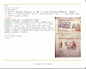
  <figure>
    <head>Fall of the Angels</head>
    <figDesc>Above, God, cross-nimbed, beardless, and holding a closed book,
    accompanied by three angels, turns and gestures toward three angels on
    the left, one of whom (Lucifer?) holds a palm frond ...</figDesc>
  </figure>

<pb n="17"/>
Case 2: Digital Facsimile
Should be marked as a separate <TEI> element. TEI structural tags may be used, but need not be, especially if differences between textual structure and physical structure cause overlap.
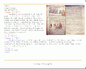
Each distinct image making up the facsimile should be encoded as a <figure> element, arranged in the normal reading sequence of the facsimile. The appropriate milestone element (<pb/> or <cb/>) should be used at the appropriate place in the facsimile.
<pb n="16"/>
<figure n="16">
    <figDesc>[Page 16: 15 lines of text followed by image of "Fall of Angels"
    (Ohlgren 16.11)]</figDesc>
</figure>
<pb n="17"/>
<figure n="17">
    <figDesc>[Page 17: 15 lines of text followed by image of  "Fall of Angels"
    (Ohlgren 16.12)]</figDesc>
</figure>
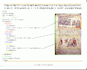
<figure> elements may be self-nested to show that one image logically contains others (in cases where two image fit together to form one larger image).
<figure n="16">
  <figDesc>
    <figure>
      <figDesc>[Page 16: 15 lines of text (detail of upper part)]</figDesc>
    </figure>
    <figure>
      <figDesc>[Page 16: Image of "Fall of Angels" (Ohlgren 16.11) (detail of lower part)</figDesc>
    </figure>
  </figDesc>
</figure>
3: Techniques for Referencing Images
Recommends declaring the file containing the image as an external entity and then referencing that entity using the "entity" attribute in <figure>. This approach depends on the use of the DTD (no longer practical given the TEI's move towards using the RelaxNG schema), and relies on an attribute that is no longer included in P5.
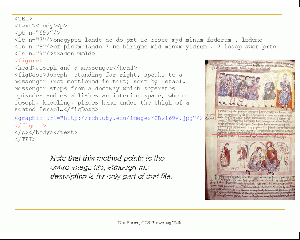
In TEI P5 there are also two new elements, <graphic> and <binaryObject> which may be used to represent image references or images respectively. These permit the encoding of figures containing multiple images, for example. The <graphic> element has a "url" attribute which enables the association of a <figure> with its corresponding image file. The recommendations in Gartner and Burnard need to be revised substantially in this respect.
<pb n="16"/>
<figure n="16">
    <figDesc>[Page 16: 15 lines of text followed by image of "Fall of Angels"
    (Ohlgren 16.11)]</figDesc>
    <graphic url="http://image.ox.ac.uk/images/bodleian/msjunius11/16.jpg"/>
</figure>
<pb n="17"/>
<figure n="17">
    <figDesc>[Page 17: 15 lines of text followed by image of  "Fall of Angels"
    (Ohlgren 16.12)]</figDesc>
    <graphic url="http://image.ox.ac.uk/images/bodleian/msjunius11/17.jpg"/>
</figure>
<figure> may contain more than one graphic, so it is possible to relate multiple image files to a single physical object:
            <pb n="16"/>
            <figure n="16">
                <figDesc>[Page 16: 15 lines of text followed by image of "Fall of Angels" (Ohlgren
                    16.11)]</figDesc>
                <graphic n="daylight" url="http://image.ox.ac.uk/images/bodleian/msjunius11/16.jpg"/>
                <graphic n="uv" url="http://image.ox.ac.uk/images/bodleian/msjunius11/UV/16.jpg"/>
            </figure>
            <pb n="17"/>
            <figure n="17">
                <figDesc>[Page 17: 15 lines of text followed by image of "Fall of Angels" (Ohlgren
                    16.12)]</figDesc>
                <graphic n="daylight" url="http://image.ox.ac.uk/images/bodleian/msjunius11/17.jpg"/>
                <graphic n="uv" url="http://image.ox.ac.uk/images/bodleian/msjunius11/UV/17.jpg"/>
            </figure>
Other options mentioned in the recommendation: Xlink or Xinclude.
4: Aligning transcription and facsimile
The TEI Guidelines propose a number of methods for aligning parts of a document (see www.tei-c.org/Guidelines/SA). These may be briefly summarized as follows
- use the @corresp attribute to assert that a <pb> (or other reference point) in the transcription corresponds with a <pb> in the facsimile (or the reverse);
- alternatively, use a stand-off <link> element to assert the association between the two <pb> elements;
- for cross-document linking, an intermediate <xptr> may be used as the target.
(see Chapter 14 Linking, Segmentation, and Alignment).
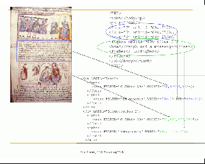
Method used by Edition Production & Presentation Technology (EPPT) to link images and text with complex markup
EPPT (http://www.eppt.org/eppt-trial/EPPT-TrialProjects.htm) is a software platform designed to help editors prepare and display image-based XML-encoded electronic scholarly editions. EPPT uses electronic text, DTDs, and digital facsimiles (JPG, BMP, GIF, TIFF, etc.) to produce highly complex encoding of image-based textual resources. EPPT supports any DTD-based encoding schema (such as the TEI P4 DTDs – with support for P5 XML Schema and RelaxNG currently under development) and enables precise, semi-automatic linking of full images as well as image sections with structural and descriptive metadata. EPPT includes new technologies and extensions (such as support for multiple hierarchies) to provide a powerful user interface for leveraging XML technologies in the production of image-based XML-encoded electronic editions.
Main features of EPPT
- Starts new projects quickly through a project wizard
- Customizes different projects using different schemas
- Carries the data management burden (XML syntax, well-formedness, etc.), allowing the editor to focus on the content, and how and where to encode it
- Provides simple user interfaces to link images and text through markup:
- Select text
- Select corresponding section of image
- Select element from DTD-sensitive interface which opens an element-specific template
- Fill in desired attribute values
- Click “Tag it!”
- Uses templates to reduce errors, ensuring comprehensive insertion of markup, and acceleration and, in some cases, automation of the insertion of repetitive attribute values
- Offers easy navigation of text, metadata, and images
- Supports multiple XML hierarchies in the same project with serialization in XML using "milestones" and "fragmentation” (as described in the TEI guidelines)
- Allows grouping of tags into semantically related markup categories for easier project management, collaborative editing, distribution of effort, etc.
- Integrates XSL and generates HTML presentations
- Provides an API (with examples) to link HTML presentations (through XSLT) with project images and text, extracted and displayed from markup
- Furnishes individual views of text content and its markup, and filters for both, to help the editor focus on particular content or markup as the encoding grows
- Operates on XML and produces non-proprietary XML completely portable to other applications
- Can extract rectangular sections of images to be used in HTML presentations based on image X/Y coordinates stored in the markup
- Includes a customizable search interface with an XQuery search engine
EPPT Tools
ImagText
ImagText, the default user interface of EPPT, is responsible for both image data management (e.g., finding and opening image files associated with a project) and user image-interface interaction. The tool provides the usual image manipulation toolbox: zoom, magnification, horizontal or vertical display of one or two images, etc.
ImagText supports image area selection and, provided the @coords has been included in the content model for the selected element in the DTD, automatically inserts the X/Y coordinates of an image or image area into the markup. ImagText can also extract sections of an image based on the coordinates’ data in the markup. This feature is particularly applicable to the creation of dynamic HTML presentations enhanced with these image fragments without the need to create the image fragments manually in advance.
Overlay
Multiple images of the same manuscript folio or book page, each captured under different lighting conditions, may reveal details otherwise not visible in a single image (such as different layers of a painting). The EPPT OverLay tool creates a single image from two overlaid images for comparing and encoding multiple images of a folio or page. The tool includes a slider which changes the transparency of the top image, thereby making the bottom image gradually visible.
Overlaying two images is a simple process. The user selects a pair of points for each image; OverLay then automatically scales the images until the selected pair of points from both images coincides to create the resulting overlaid image. OverLay enhances image-based electronic editions in at least two ways:
i. Overlay allows comparison of multiple images of the same object. For example, when studying images of a palimpsest captured under different lighting conditions, such as bright daylight and ultraviolet fluorescence, Overlay allows the editor to compare and contrast the readable text in one or both images simply by selecting a portion of the overlaid image and moving the slider.
ii. Overlay allows encoding image-text correspondence for one reference image; the other images of the same object are then "scaled" to the reference image so that all related image-text correspondences are accurate.
An overlaid image can be saved and attached to a project, thus automatically remaining available for future encoding.
xTagger
xTagger is a document-centric XML editor with built-in options to display or hide XML syntax from the user. In xTagger, markup is inserted by first selecting the text, then adding element and attribute information through a template interface called xMarkup. The editor focuses on how and where to encode, leaving the burden of XML syntax correctness to xTagger.
The following is a list of most important features of xTagger:
- Provides content-only and/or XML-view of the edition
- Allows the editor to define filters for hiding text and/or markup, useful for complex projects including textual variants, editorial emendations and annotations, expansion of abbreviations, etc.
- Supports XML markup search and text search
- Includes configurable tool tip information, formatted in HTML, which facilitates quick viewing of metadata simply by moving the mouse pointer
- Provides links from text to its corresponding image via the @coords X/Y coordinates
- Supports integration of multiple XML hierarchies (i.e., more than one XML schema can be associated with a project) through XML serialization using milestones and fragmentation
xMarkup
xMarkup comprises multiple templates – one for each element in the DTD(s) associated with a project – which support quick encoding of text and semi-automatic linking of images and text. Each template includes all the attributes associated with an element and when applicable, a list of all enumerated values associated with a specific attribute. xMarkup also supports customization of markup hierarchies and association of aliases to elements (e.g., line for <l>) to simplify markup for novice text encoders. xMarkup can be used not only for inserting markup, but for editing and/or deleting markup as well.
HttpServer
HttpServer is a lightweight HTTP server implemented in EPPT to support HTML presentation of XML data. For instance, HTML pages displayed in EPPT can request image fragments from ImagText, based on image fragment coordinates stored in the XML markup as the value of the @coords. The tool is extremely useful in editorial work as it facilitates dynamic transformation of an XML-encoded edition into an HTML presentation with integrated images and text. An editor can view the images and text in HTML, then seamlessly return to the project view to make corrections and/or revisions to the markup.
Image-Catalog
An important feature of image-text linking in EPPT is the decoupling of image identifiers that appear in the markup (e.g., <div n=“f123v”>) from the actual image file names (e.g., “f123v.jpg”). To facilitate this, EPPT uses an image file indexer called the image-catalog. The image-catalog maintains correspondence between the image identifiers used in the markup and actual image files, and determines whether or not a given image file belongs to a project. For example, a project may include multiple images of the same folio or page, such as images captured under different lighting conditions. In such cases, both images will have a single identifier in the markup: the user simply decides which specific image of that page or folio to display.
Additional Tools
Other tools provided in EPPT include:
- DucType
- Glossary Tool
- StaTend
- Quires
Method used by the UVic Image Markup Tool: Annotate images
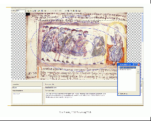
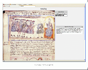
The UVic Image Markup Tool (http://www.tapor.uvic.ca/~mholmes/image_markup/) uses TEI, modified to allow for the inclusion of SVG (http://www.w3.org/Graphics/SVG/), to create a system for annotating images.
Stated goals of the Tool:
- be simple for novices to use
- load and display a wide variety of different image formats
- allow the user to specify arbitrary rectangles on the image, and associate them with annotations
- allow such rectangles to overlap if the user wishes
- provide mechanisms for bringing overlapped rectangles to the front easily
- allow annotations to be grouped into categories, distinguished by name and appearance, to allow different classes of annotation
- require no significant knowledge of XML or TEI
- allow the use of XML code if the user wishes
- save data in an XML file which conforms to a TEI P5-based schema
- reload data from its own files
- generate a simple "Web view" of the data for display in a browser
- come packaged with an installer, Help file, and basic tutorial
- be simple for novices to use!
Simplified example from the IMT web:
<TEI>
    <teiHeader>
        <!-- ...header content... -->
    </teiHeader>
    <text>
        <body>
            <!-- ...TEI content... -->
            <div type="imtAnnotatedImage">
                <svg xmlns="http://www.w3.org/2000/svg">
                    <!-- ...svg content... -->
                    <image>
                      <!-- Image file is linked in here -->
                    </image>
                    <rect>
                      <!-- Annotation area on the image defined here -->
                    </rect>
                </svg>
                <div type="imtAnnotationLayer">
                    <!-- Annotation content goes here -->
                </div>
            </div>
            <!-- ...TEI content... -->
        </body>
    </text>
</TEI>
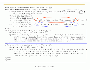
Using this system, a user can annotate many sections of a single image. Unlike the EPT system described above, in which the coordinates are stored directly in the element, here the image coordinates are stored in a separate section and linked to the annotations using unique IDs (svg:id in <rect>) to link the areas to the annotation content (n in <div type="imtAnnotationLayer">).
<div type="imtAnnotatedImage" xml:id="NB-B-17328">
    <svg xmlns="http://www.w3.org/2000/svg">
        <image xmlns:xlink="http://www.w3.org/1999/xlink" xlink:href="NB-B-17328.jpg" width="5060" height="6025"/>
        <title>NB-B-17328.jpg</title>
        <desc>5060 x 6025</desc>
        <rect svg:id="NB-B-17328_0" x="4287" y="1412" width="580" height="426" style="3" color="#ff0000"/>
        <rect svg:id="NB-B-17328_1" x="4067" y="2019" width="720" height="747" style="3" color="#ff0000"/>
    </svg>
    <div type="imtAnnotationLayer" n="NB-B-17328_0">
        <head>la chandelle allume la découverte.</head>
        <p>Il a trouvé la cache.</p>
    </div>
    <div type="imtAnnotationLayer" n="NB-B-17328_1">
        <head>le couvercle de la malle</head>
        <p>Il est pris sans vert</p>
    </div>
(TEI examples from the UVic file example: http://www.tapor.uvic.ca/~mholmes/image_markup/Amant.xml)
For more details on the TEI/SVG used by the IMT, see here: http://www.tapor.uvic.ca/~mholmes/image_markup/xml.php
Using METS to link text and image
What is METS?
- Metadata Encoding and Transmission Standard (http://www.loc.gov/standards/mets/)
- “a standard for encoding … metadata regarding objects within a digital library”
- Centered at the Library of Congress
- Developed out of the metadata specs from the LOC’s “Making of America 2” project (MOA2)
- Developed by librarians and archivists, for librarians and archivists
- Accepted standard with a broad user base (http://sunsite.berkeley.edu/mets/registry/)
- Unrelated to TEI
While a library may record descriptive metadata regarding a book in its collection, the book will not dissolve into a series of unconnected pages if the library fails to record structural metadata regarding the book's organization, nor will scholars be unable to evaluate the book's worth if the library fails to note that the book was produced using a Ryobi offset press.” (METS: An Overview and Tutorial)
Why METS?
- System to organize disparate parts and relate files (and pieces of files):
- Areas on images correspond with sections of text
- Areas on images relate to one another
- Areas of text relate to one another
- METS provides sections for defining the logical and/or physical structure of the digital object
- File Section (fileSec)
- Structural Map (structMap)
File Section
“lists all files containing content which comprise the electronic versions of the digital object.”
- Similar to the EPT Image Catalog
Within the FileSec
- FileSec consists of Groups of File Locaters
- File Group: contains related files
<fileGrp USE="facsimile">
- File: assigns the individual files unique identifiers
<file ID="C-Clbiv-69v" MIMETYPE="image/tiff">
- File Locater: points to the location of the file, using xlink syntax
<FLocat LOCTYPE="URN" xlink:href="images/C-Clbiv-69v.jpg"/>
Example (Images)
<fileGrp USE="facsimile">
  <file ID="C-Clbiv-69v" MIMETYPE="image/tiff">
    <FLocat LOCTYPE="URN" xlink:href="images/C-Clbiv-69v.tif"/>
  </file>
  <file ID="C-Clbiv-70r" MIMETYPE="image/tiff">
    <FLocat LOCTYPE="URN" xlink:href="images/C-Clbiv-70r.tif"/>
</file>
…
</fileGrp>
Example (Transcript)
<fileGrp USE="transcript">
  <file ID="id-pref-genesis" MIMETYPE="text/xml">
    <FLocat LOCTYPE="URN" xlink:href=“transcription/pref-genesis.xml"/>
  </file>
  <file ID="id-genesis" MIMETYPE="text/xml">
    <FLocat LOCTYPE="URN" xlink:href=“transcription/genesis.xml"/>
  </file>
  <file ID="id-exodus" MIMETYPE="text/xml">
    <FLocat LOCTYPE="URN" xlink:href=“transcription/exodus.xml"/>
  </file>
…
</fileGrp>
Structural Map
“outlines a hierarchical structure for the digital library object, and links the elements of that structure to content files … that pertain to each element.”
- Organization may be logical or physical
- A single METS file may contain multiple structural maps
Within the StructMap
- StructMap consists of organizational divisions, that may nest
<div LABEL="Genesis" ORDER="2">
  <div LABEL="Folio 1v" ORDER="2">
   ...
  </div>
</div>
- The divisions contain pointers to the files, and areas of files, indexed in the fileSec
<div LABEL="Genesis" ORDER="2">
  <div LABEL="Folio 1v" ORDER="2">
    <fptr FILEID="C-Clbiv-1v"/>
    <fptr>
      <area FILEID="id-genesis" BEGIN="1v.32" END="1v.38"/>
    </fptr>
  </div>
</div>
Example (Basic)
The first file pointer references the corresponding image file, while the second one references the corresponding line range (BEGIN and END) in the XML file (these are the values of, for example, @xml:id on <lb/>
<div LABEL="Folio 69v" ORDER=“139">
  <fptr FILEID="C-Clbiv-69v"/>
  <fptr>
    <area FILEID="id-genesis" BEGIN="69v.1" END="69v.12"/>
  </fptr>
</div>
<div LABEL="Folio 70r" ORDER="140">
  <fptr FILEID="C-Clbiv-70r"/>
  <fptr>
    <area FILEID="id-genesis" BEGIN="70r.1" END="70r.38"/>
  </fptr>
</div>
Example (Advanced)
- <area>: reference coordinates within an image file.
- especially useful for extensively illustrated manuscripts
- create links between text and image.
- @COORDS in <area> for image files
- @BEGIN and @END in <area> for XML/TEI files
- Simplifies encoding:
- no need to define @COORDS to clutter up the TEI;
- no need to find a place to store a linking section in the TEI file
- no need to use the SVG namespace
- separate the objects (image and XML files) from the indexing of their relationships with one another
 <div LABEL="Folio 69v" ORDER="139">
  <div LABEL="Annotation 1"
    <fptr>
      <area FILEID="C-Clbiv-69v" COORDS="40,12,975,121"/>
    </fptr>
    <fptr>
       <area FILEID="id-genesis" BEGIN="69v.annot.1"/>
    </fptr>
  </div>
  <div LABEL="Illustration 1">
    <fptr>
      <area FILEID="C-Clbiv-69v" COORDS="96,87979,572"/>
    </fptr>
    <fptr>
       <area FILEID="id-genesis" BEGIN="69v.illus.1"/>
    </fptr>
  </div>
  <div LABEL="Text">
    <fptr>
      <area FILEID="C-Clbiv-69v" COORDS="71,531,978,859"/>
    </fptr>
    <fptr>
      <area FILEID="id-genesis" BEGIN="69v.1" END="69v.9"/>
    </fptr>
   </div>
  </div>
ALTO
ALTO (Analysed Layout and Text Object) is an extension schema for METS, allowing the markup of layout information of digitised texts. It has had a bit of use in newspaper digitisation in the States, in the National Digital Newspaper Project.
In summary, it defines digitised texts as consisting of "page" elements containing "blocks" which have rectangular coordinates assigned to them using attributes HPOS, VPOS, WIDTH, and HEIGHT, and also a ROTATION. Each block element's page is associated with image files with stand-off markup in the normal METS way.
By contrast we need a different way to relate TEI content elements to pages, since the dominant hierarchy in TEI is logical rather than physical (i.e. div rather than page).
Conclusions
- Draft Recommendations for TEI Digital Facsimiles
- Not robust
- No specific image/text linking
- Based on TEI P3 (though updated on this page to TEI P5)
- Edition Production Technology (EPT)
- Designed for textual annotation, but can annotate illustrations as well
- Markup schema is not defined - editors can use their own markup schemas (requires @coords)
- Complex
- Dependent on editing software
- Supports most image file formats (jpeg, tiff, gif, bmp)
- No visualization outside of the editing environment
- UVic Image Annotation Tool
- Simple
- Annotates via description – no “text encoding” (i.e., cannot include in an electronic transcription)
- Based on accepted standards
- Markup schema is defined (extended TEI + SVG)
- Visualization through SVG-enabled browser
- METS
- Very complex
- Objects separate from indexes
- Flexible – can link many textual and image sections (Venetus A – link main text and several layers of annotations)
- No visualization (yet) for the more advanced image-text links
